|
|
Previous Next
8.2 Edit MenuUndo - Ctrl+ZUse this command to reverse the last command you used. This can be done repeatedly until the point at which you created this layout, or last saved it. When you save a layout, the undo information is cleared. See Redo command. This only applies to the current document. Redo - Ctrl+YSimilar to Undo, the Redo command will peform previous actions that were saved in the Undo/Redo history. You can go back and forth through the Undo/Redo stack if you want to review these actions. But if you break the chain by performing a new action after Undoing, you will not be able to Redo those original steps. This only applies to the current document. Cut - Ctrl+XSelecting Cut will delete the selected object(s) (text, logo, loop, vector, etc.) from the layout and places it into the Clipboard, erasing the previous Clipboard contents. Use Paste to place the cut image in the same layout, another layout, or another application. You can also select this command by double clicking and holding down the mouse button, as you hold down the button move the cursor to the word Cut and release the button. Copy - Ctrl+CSelecting Copy will copy the selected object(s) (text, logo, loop, vector, etc.) from the layout and places it into the Clipboard, leaving the original intact and erasing the previous Clipboard contents. Use Paste to place the copied image in the same layout, another layout, or another application. You can also select this command by double clicking and holding down the mouse button, as you hold down the button move the cursor to the word Copy and release the button. Paste - Ctrl+VSelecting the Paste command will allow you to copy the contents of the Clipboard into LED Wizard. You can paste something that was Cut or Copied from LED Wizard or other applications like Corel Draw or Adobe Illustrator. There's a PDF clipboard format available, where Paste operates with some more options. You will see the following dialog box appear, where you choose the same options that you see when importing a PDF file. 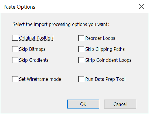
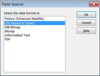
Original PositionPaste using the original position Skip BitmapsIgnore bitmaps in the PDF document. Usually bitmaps aren't needed in creating LED layouts. Skip GradientsIgnore gradient fills in the PDF document. Gradients are not needed in creating LED layouts. Reorder LoopsReorder loops, since sometimes loop directions are incorrect. Correct loop direction is essential proper LED layout generation. Skip Clipping PathsIgnore all clipping paths. Clipping paths can cause problems in creating LED layouts. Strip Coincident LoopsSometimes the same vector path is duplicated, and this causes problems in created LED populations Set Wireframe ModeForces full colors to be turned off, in cases where the letters came from a clipping mask and didn't have a full or stroke. Without this checked, you might think nothing was imported if you started with fill colors shown. Run Data Prep ToolRun the Data Prep tool immediately after importing. Paste SpecialSelect this command to paste something else besides the default data type. For example, if there is a metafile and a bitmap in the clipboard, and the normal Paste command only pastes the metafile, but you really want the bitmap, select Paste Special and choose the bitmap instead.
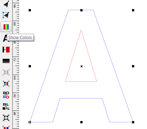
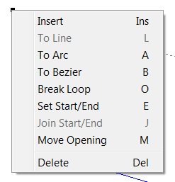
Note: PDF will include vector data from an application such as Adobe Illustrator or Corel DRAW. Paste in PlaceThis command will paste an LED Wizard object into the current layout so that the size and position remains the same as the original object. This will not be available when other data types are used, such as EMF or a bitmap. Delete - DelThe Delete command is the same as Cut, in that the object or group of objects that is selected will be removed, but the selected objects will not be placed in the Clipboard. You can replace the deleted objects by selecting Undo. You can also select this command by double clicking and holding down the mouse button, as you hold down the button move the cursor to the word Delete and release the button. Duplicate - Ctrl+DThis command will allow you to duplicate the select object(s). The new object(s) will be offset by 1/3 of the width in the X-axis and 1/3 of the height for the Y-axis. You can Duplicate a populated object, but you must be in the Layout Tool and not PowerFlow. You can also Duplicate a Group of a populated object and its loaded power supplies. Select All - Ctrl+AThe Select All command selects every object in the layout. This does not include guidelines. Vector/Node ToolsThere are a number of vector/node editing tools in LED Wizard 8 that you can access while in the Vector Edit Tool. This is located in the toolbox along the left side of the screen, second icon from the top. When you're in the Vector Edit Tool, double click on a vector or point to bring up the pop-up menu that contains the available tools. Note the shortcut keys for common tasks - you can use these directly without the pop-up menu.
There is also additional help for the Vector Edit Property Bar, which is displayed when you are operating in the Vector Edit Tool. Please note that once you have populated an object with LEDs, you can no longer vector edit. Vector - Insert - InsThe Insert command will insert an Arc, Line or Bezier Curve into the currently selected object, depending on the object selected. Example: If you have an Arc selected, then select the Insert command, another Arc will be inserted at that point. If you have a Bezier Curve selected and you select Insert, then another Bezier Curve will be inserted. Inserting an Arc, Line or Bezier Curve
The vector will be broken at the point where you selected. If you have an Arc selected, an Arc will be inserted. If you have a Line selected, a line will be inserted. If you have a Bezier Curve selected, a Bezier Curve will be inserted. Vector - To Line - LThe To Line command will allow you to select an Arc or Bezier Curve and turn it into a Line. Turning an Arc or Bezier Curve into an Line
Vector - To Arc - AThe To Arc command will allow you to select a Line or Bezier Curve and turn it into an Arc. Turning a Line or Bezier Curve into an Arc
Vector - To Bezier - BThe To Bezier command will allow you to select an Arc or Line and turn it into a Bezier Curve. Turning an Arc or Line into a Bezier Curve
Vector - Break Loop - OThe Break Loop command will allow you to break the currently selected loop. This is necessary if you wish to join to characters or objects together. To Break a Loop
To Join a Broken LoopSelect one of the points on the broken loop and move it towards the point you wish to join it to. When you get close to the point you wish to join it to, press and hold down the Shift key. You will hear a beep when the two points have joined. When you break a loop, the start/end point is moved to the location that you broke the loop. If you are joining two points, only one of them can be a start/end point (can't join two start/end points). If you have selected a point that is not the start/end point, it can only be joined with a point that is a start/end point. Vector - Set St/End Point - EThe Set St/End command will set the currently selected point as the Start/End point, moving it from another point. Vector - Join St/End Point - JThe Join St/End command will connect the currently selected end point of an open loop to another open loop end point. Start by clicking on the end point that you want to connect, then select Join St/End. The selected point will now be attached to the position of the mouse. Move the point to the other end point and it will snap to the same position. Now release the mouse button and the loop will be closed. If you select a point that is not the end point of an open loop, then this function will not be available. If you are trying to connect an open loop of one object to an open loop of another object, those two objects must be Combined for this to work. Vector - Move OpeningThe Move Opening command will move (or create) the opening of a loop to the selected location. The traditional usage for this function is to move the opening of a loop from one location to another. In so doing, the original opening will be closed. An alternate way to use this tool is simply to open a loop at the specified location from a normal closed loop. Vector - Add Vertical Guide - Shift+Ctrl+VVector - Add Horizontal Guide - Shift+Ctrl+HReorder LoopsThe Reorder Loops command will reorder all the loops in the selected object so that they are properly ordered as follows:
This is critical to the correct population of the artwork. There are multiple opportunities to Reorder Loops when you import your artwork, but you can always run this function in the Edit Menu. If after running this function, the loops do not order correctly, you can use the Loop Edit Tool to change the direction of an individual loop. Unexplode Vector PathsThis tool will connect "exploded data" that is associated with a certain type of DXF file. The functionality is this tool is included in the larger Data Clean Up Tool that is run when you import custom artwork, so please review the documentation there. Purge Undo/HistoryIf you are working on a file for a particurly long time and/or you have a large, complex file, the Undo/Redo history stack can consume a lot of computer memory. This function will purge the Undo/Redo steps and release that memory. After you do this, you will not be able to Undo/Redo, but you will begin a new history of steps from that point forward. Document PropertiesThe Document Properties dialog box will appear when you launch a New file in LED Wizard 8. There are several items here that you can specify for the document. 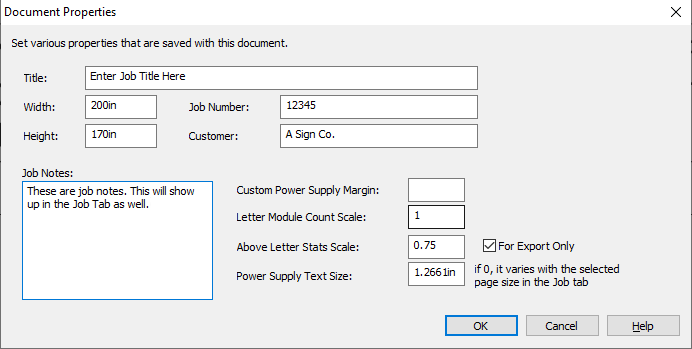
TitleThis is the title of the document. If you enter a title here, it will go into the title block title field. Width and HeightYou can set the Width and Height of your new layout here, if it is different from your default. Job NumberIf the layout has a specific job number, enter it here. CustomerEnter the customer name here. Job NotesEnter any job specific notes here. The text you enter here will also be displayed in the Job Tab (and can be edited directly in the Job Tab). Custom Power Supply MarginIf your layout has different power supply loading requirements from the defaults, then you can enter the custom margin here. The "Margin" value is a percentage of the driver capacity that would not be loaded. So if you want to load your drivers to 80%, then you would enter 20% in this field as the margin. If there is no value in this field, then the default value will be used for the driver you select. Letter Module Count ScaleThis value will make the module count data under the letters larger or smaller. The default value is 1. A value larger than 1 will make these numbers larger, while a value of less than 1 will make them smaller. Above Letter Stats ScaleThe value will make the Above the Letter Stats larger or smaller. These stats are dynamically generated according to the selections you've made in the Options dialog box, LED Tab. The default value is 0.75. The size of the Above the Letter Stats should at least partially be determined by how many of the stats you are displaying, since the stat object will be longer if you have several of the stats selected. You can select the Above the Letter Stats that you want in the Options dialog box from the Tools Menu, LED tab. Power Supply Text SizeYou can enter a specific size here that will be a constant size for the power supply text boxes, such as 1 or 2 inches. You may find with larger layouts that you need these labels to be larger however. If you enter a value of 0 here, then you can instead select the the appropriate Page Size in the Job Tab of your exported PDFs, and that will scale the power supply text size appropriately so that is legible at that page size on the final PDF. Previous Next |
 Please see additional topics in this section for a description of each option.