In LED Wizard 7.1, we introduced the Router Layer function that creates a series of lines in the position of each LED for export to the router. This is an invaluable feature for helping to produce the channel letters, ensuring that modules are positioned accurately and speeding up the process considerably.
The primary benefits to creating and exporting the Router Layer are twofold:
- Accuracy of the actual module placement in the letters or cabinet in relation to the layout.
- Efficiency of mounting the modules.
The Router Layer is the primary method of connecting the estimate of the job with the production of the job.
LED Wizard 8 adds valuable new options to the Router Layer production feature. Originally, the Create Router Layer function made short lines in the exact position of each LED. Now it also includes a Continuous Path, with or without "Notches" to indicate the position of each LED. The primary advantage here is that the router doesn't have any Up movements, therefore considerably increasing the productivity of this task.
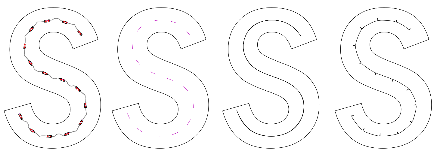
The first letter S shows the original module layout. The second S is the traditional data of a line in the position of each LED. The third S shows a smooth, continuous path of the modules. The fourth S shows the continuous path with notches in the center of each LED position (notches in this case were made larger than necessary for viewing).
After you have made a layout using the auto layout and/or semi-auto layout tools, you can convert the module path into an open loop vector object with this function.
LED Wizard does not contain direct support for outputing to a router, but you can export your files to router-compatible formats such as DXF.
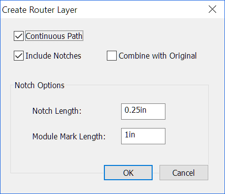
Continuous Path
Checking this will enable the other options in this dialog box. With this unchecked, it will create simple broken lines where the modules are located, as in version 7.x. Again, creating a continuous path is more efficient for routers because the up and down motion is eliminated.
Include Notches
Check this option if you want to include "notches" that show the center position of each LED. This is an alternative to the original Router Layer function, but with a continuous path. Uncheck this option if you want a smooth vector path, without an indication of the exact position of each LED. This smooth path could be used as a tool path to route out the back of acrylic letters for a string of LEDs, for example.
Combine with Original
Check this option if you want the vector path to be Combined with the original letter or graphic. Uncheck this option if you want the newly created vector path to be a separate object from the original letter or graphic.
Notch Options
If you have Include Notches checked, then you can set the size of the notch and the straight line representing the module.
Notch Length
This is the length of the notch that indicates the position of each LED. It does not have to be very long, perhaps only .25" to .5" (8-12mm).
Module Mark Length
This is the length of the straight line that represents the module. This should not be longer than the module itself.
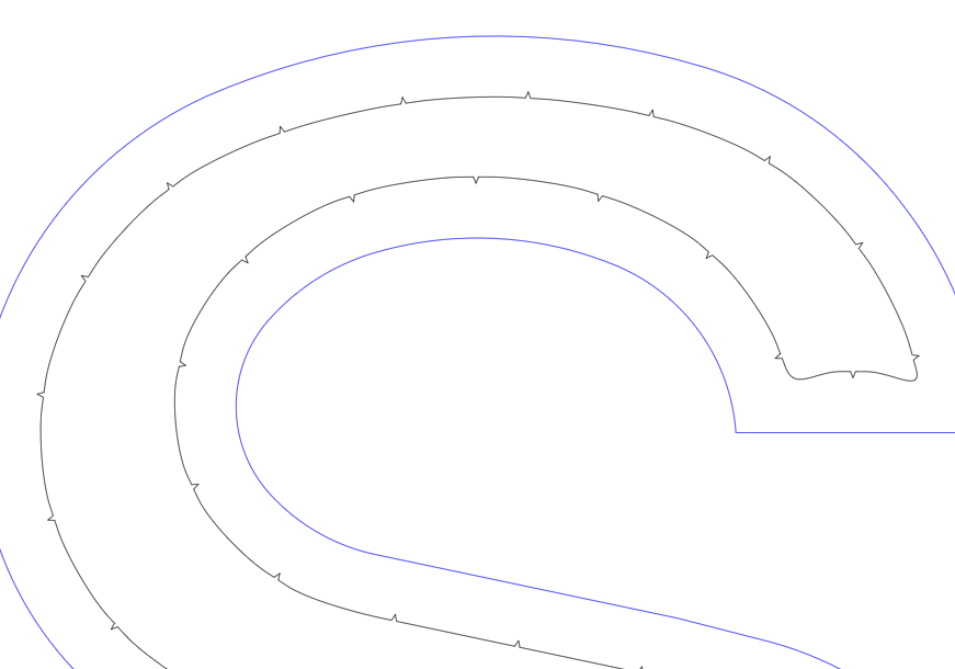
This example shows a vector module path with notches, combined with the original letter.
There are various ways to utilize this vector data, including the following:
- Route out the path in acrylic or other material to create a channel to place your LEDs (no notches).
- Plot, etch, or mark the position of the LEDs for production (with notches).
Creating the Router Layer is actually one of the last things you should do in the workflow. There should not be any module editing after creating the router layer (the router layer will not be updated with module positioning changes).
This function works on all modules in the layout in one step. It is different from most functions in that you do not have to make a selection first.
When you export, this data will be in the layer called "Module Markings." For an export to a scaled PDF, you would want to turn this layer off. For a full scale export to a DXF, turn this layer on. See [[Export]] for more information.
The presence of the Router Layer will not impact any of the Stats data, such as Area or Perimeter.
 LED Wizard 8 Documentation