
|
|
Previous Next
7.1.2 PowerFlow Property BarThe PowerFlow Property Bar contains many functions and options for creating LED layouts. When you launch PowerFlow, this property bar will appear across the top of the screen. 
The first four drop down lists at the top left of the property bar are filters for helping you select the right LED module. They are, from left to right, Brand, Series, Color, and Depth, and are designed to be selected in that order.
The first drop down list box on the left side is used to select the Brand of the LED module to use.
The second drop down list box on the left side is used to select the module Series of the Brand you've chosen. A Series is defined as modules that differ only by color or white color temperature.
The third drop down list box on the left side is used to select the module Color within the Series you've selected. It is possible that a Series only has one color, normally white.
Select the can depth here. This is the final filter for the module list, and is used to determine the correct density guidelines, such as the recommended number of runs per stroke, module spacing/modules per foot, run gap and clearance settings, as specified by the supplier of the selected module.
This is the list of the modules that is the result of the four filters that you have selected. In some cases, only one module will be in the list, in which case it will be automatically selected. In other cases, you can scroll down and select the module that you want to use.
This is the maximum stroke width calculated from the vector graphic (usually a single letter). This is used as an input to the density guidelines to automatically calculate the module spacing, number of runs (rows), the clearance, and run gap, if applicable. You can change this value either by entering a new one, or by using the Calculate Stroke Width at Cursor feature (position the mouse inside the letter where you want to measure and press ALT+S).
The Clearance value is the distance from the return to the first run in the stroke. It is a calculation based on the Stroke Width and the number of Runs of the selected object. If the number of Runs is 1, then the Clearance value is 0, and the run is in the center of the stroke. If the number of Runs is 2, then the Clearance value is 25% of the measured Stroke Width. In this example, the Stroke Width is 10", and the Clearance value is 2.5" Imagine a line down the middle of the stroke, dividing the stroke into two 5" sections. We then have two runs, evenly distributed in each section. 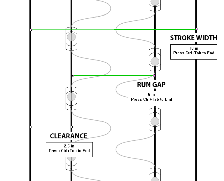
If the number of runs is 3, then the Clearance value is 1/6 of the Stroke Width. 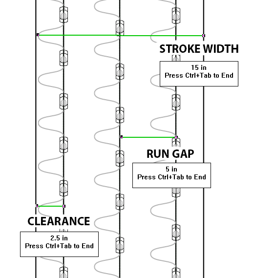
You can override the Clearance value and make adjustments to the above rules of thumb.
As per the graphics above, this is the automatically calculated gap between runs or rows, based on the stroke width and number of runs. Note that the Run Gap is not necessarily consistent across a letter, but the Clearance value is. Or to put this another way, on a variable stroke letter, it is the Run Gap that varies, not the Clearance.
In order to create even spacing for the widest stroke, the actual run gap used can be different from the value in Run Gap, above. This field is read only because it's automatically calculated. You can change this by entering different values for Clearance or Run Gap. In the case of a parallel cabinet layout, you can fix the Run Gap value and make the Clearance value vary. See below for more details.
This is the total number of runs, or rows, to be created for the widest stroke. This is automatically calculated from the Density Guidelines for the selected Module, Stroke Width, and Can Depth. You can override this value if you feel that the default suggestion is wrong for your application.
This is the diameter of the stroke circle that's drawn around the cursor to help you estimate how many modules should be placed within the stroke. You can change the number directly in this field, and also use + (plus) or - (minus) keys to change this value in 1 inch increments. Press the N key to toggle the stroke circle display on and off.
With this checked, which is the default, the population will be created according to the Density Guidelines. This option is extremely important, and version 8 is very complete and accurate in this regard. If this is unchecked, then you can determine the density guidelines manually. Any manual adjustment of Clearance, Run Gap, or Number of Runs will uncheck Auto Calc for that object. If you have a set of letters and you want to populate the entire set with your new denisty guidelines, then be sure to check Locked (see below). The primary concern with this option is indavertently unchecking the option and not realizing it, and then making a whole layout with the wrong settings. Try to get in the habit of noticing this check box. We have highlighted it when off to help you notice it. This is not to say that going off the density guideliness is necessarily bad. There are plenty of reasons for going off the recommended density guidelines. Two of the most common are that the layout is a Halo Lit layout, and so the Clearance value is smaller, or that the layout just needs to be brighter, and maybe you're putting in an extra run of LEDs. DensityWhen this is checked, the current values have been loaded from the density database. Use the "D" button to load the density settings for the selected module and stroke width / can depth combination. When this is unchecked, the current values have not been loaded from the density database. There is additional Density information in the Density Info Bar just below this PowerFlow Propetery Bar. LockedWhen this is pressed, the current object's density guidelines will be used for the whole population, such as a channel letter set. The data that is fixed includes Clearance, Run Gap, and Number of Runs. These fields will actually be grayed out to show you that those values are not editable. You would consider doing this when you want to ensure consistency across the whole letter set. For example, sometimes there are stroke width variances across letters such that, according to the density guidelines, one letter might get a single run and another letter might get a double run layout. While this might be technically accurate, perhaps it is because the measured stroke widths are right on the edge between a single and double run, and in this case it would be more important to be consistent in the brightness across all letters and decide on a single or double layout for the whole letter set. Target DensityThis is used with the Target Density features. This number is the ideal number of modules per square foot for your layout. It is not a predictive value, but rather a measure of the layout after it is created. ToleranceThis works with the Target Density field to provide a certain amount of accuracy for the Target Density. When the actual density of a segment matches Target Density, plus or minus Tolerance, the segment is drawn green. OATThis stands for "Outside Threshhold Angle," which is an angle that determines when to use a round or sharp join for "left turns" of an inline. For example, if it's set to 89 (degrees), then all sharp angles of 90 degrees or less will be rounded, and it's 90 or greater, they will be sharp. In some cases with very sharp turns (like with "A" and "W"), this can result in long arrows being formed, but in many cases it still works out well for LED layouts. 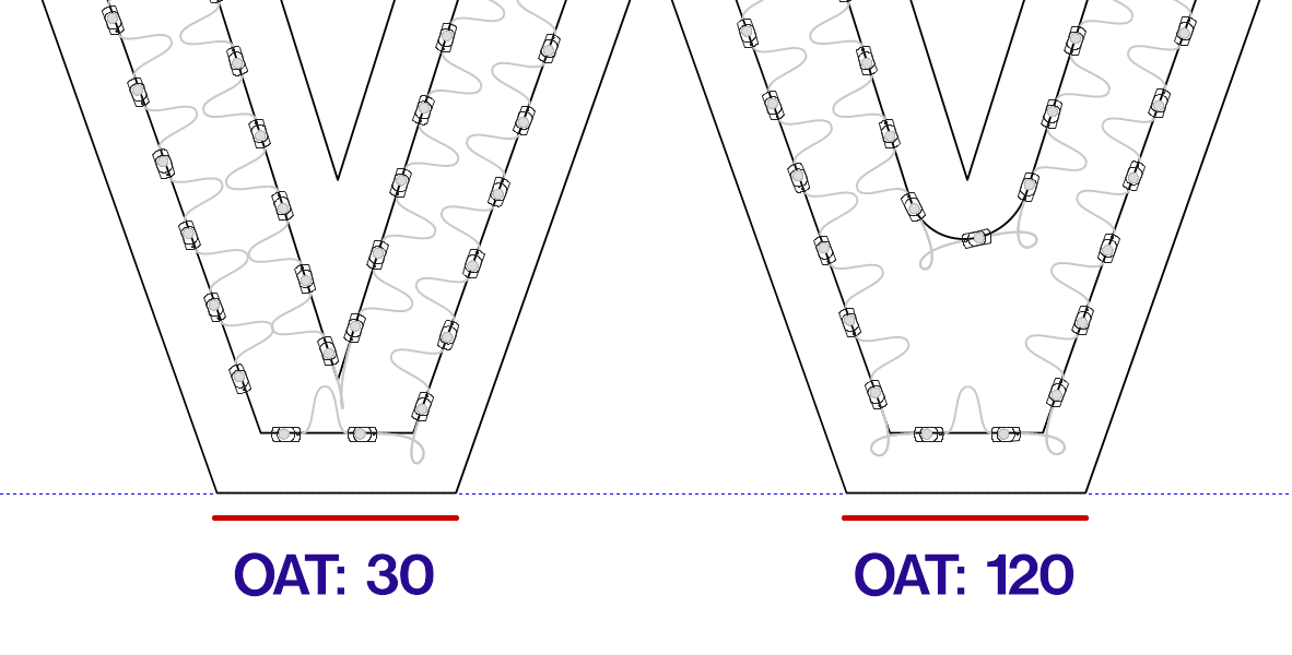
SpacingThis is the maximum spacing between modules centers, along the string of modules. It is not a Modules per Foot (or Meter) reading, but it easy to convert to that if needed. The value in this field comes from the Density Guidelines. It may be equal to the maximum possible spacing for the module when pulled tight, or it may be a smaller value, which is common as the Can Depth decreases. Many brands and modules use consistent Spacing values to make it easier for the signmaker. For example, 6" spacing is two modules per foot, 4" spacing is three modules per foot, etc. 100mm spacing is 10 modules per meter. One of the adjustments that you can make in your layouts is the Spacing value. Decrease this for tighter spacing and a brighter output. Increase it for fewer modules, but beware that you cannot enter a value that is greater than the maximum. The next several fields and icons are used to lay out modules using the Parallel Layouts option. This is often the best choice for cabinets and cloud signs, where you want straight rows of modules PRThis is the numeric rotation of the parallel guide paths. The default for parallel layouts will be horizontal (value of 0) or vertical (value of 90), but you can enter an angle here, from 0 to 360. Rotation ControlIf you prefer to set the angle manually, you can use this round control to easily set the rotation of the parallel guide paths. Just click and drag the line around inside the circle to set the angle.
|


Was this helpful?