LED Wizard 8 Documentation


Intro to LED Wizard 8 Docs
Getting Started
System Requirements
Installation
Screen Layout
LED Wizard Basics
Basic Workflow
Operating Modes
Defaults and Preferences
New in Version 8
Data Clean Up Tool
Module Filtering
LED Wizard Fonts
LED Wizard 8 Database
Population Scaling Tool
Graphical Population Scaling
Auto Stats and Title Block Merging
Auto Power Supply Loading
Auto Dimensioning
Single Run Populations
Create Guide Paths from Open Vector Paths
Freehand Drawing Tool
Power Supply Colors
New Auto Power Supply Loading Options
Multiple Document Interface
Power Supply Rotation
Population Library
Core Series Flexible Mode
Creating LED Module Layouts
Using the PowerFlow Tool
Creating and Editing LED Modules
Scaling LED Graphics
Working with Guidepaths
Working with Selections
Editing Existing Selections
Cabinet Layouts
Parallel Layouts
Module Rotations
Reusing Module Layouts
Target Density
LED Property Bar
Using Power Supplies
Using Title Blocks
Multiple Module Title Blocks
Title Block Variables
Using Guidelines
Copy and Paste
Importing Files
From Adobe Illustrator
From Corel Draw
From AutoCAD
Exporting Files
Editing Text
Zooming
Vector Editing
Loop Editing
Tools, Tabs and Property Bars
PowerFlow
PowerFlow Tool
PowerFlow Property Bar
PowerFlow Tab
PowerFlow Tool Keyboard Shortcuts
Semi-Automatic Populations
Layout Tool
Data Clean Up Tool
Auto Mounting Holes Tool
Assign Letters Tool
Scale Tab
Summary Tab
PS Tab
Objects Tab
Layers Tab
History Tab
Job Tab
Stats Tab
Text Edit Tool
Vector Edit Tool
Keys for Vector Editing
Loop Edit Tool
On Screen Digitizing Tool
Object Property Bar
Group Property Bar
Guideline Property Bar
Measure Tool Property Bar
Bitmap Property Bar
LED Object Property Bar
Job Color Property Bar
Menu Reference
File Menu
New
Open
Open Recent
Save
Save As
Save Copy As
Close
Snapshots Menu
Import
Scan
Export
Export Scaled PDF
Email PDF
Email
Print
Exit
Edit Menu
Undo
Redo
Cut
Copy
Paste
Paste Special
Paste in Place
Delete
Duplicate
Select All
Vector/Node Tools
Vector - Insert
Vector - To Line
Vector - To Arc
Vector - To Bezier
Vector - Break Loop
Vector - Set St/End Point
Vector - Join St/End Point
Vector - Move Opening
Vector - Add Vertical Guide
Vector - Add Horizontal Guide
Reorder Loops
Unexplode Vector Paths
Purge Undo/History
Document Properties
View Menu
Zoom commands
Toolbox menu
Custom Toolbars
Refresh
Show Fill Colors
Show Stroke Colors
Show Grid
Show Guidelines
Show Rulers
Show Loop Direction
Show Job Color Palette
Show Side Bar
Show Info Bar
Show Help Bar
Show Group Member Names
Highlight Small Vectors
Transparent Background
Reset Toolbar Layout
Layout Menu
Layers
Guides commands
Shapes commands
Rounded Rectangle
Polygon
Arrow
Layout Properties
Size to Fit
Show Layout Size
Snap to Grid
Snap to Guidelines
Snap Dimensions to Graphics
Selectable Guidelines
Auto Square
Create Auto Dimensions
Arrange Menu
Align Tools
Distribute Tools
Group Tools
Locked
Editable
Select Only by Edge Click
Allow Options
Break Into Loops
Break Into Outer Loops
Combine
Close All Loops
Remove All Inner Loops
Horizontal Mirror
Vertical Mirror
Z Order Tools
Move to Layer
To Top
To Bottom
Move One Up
Move One Down
Text Menu
Text Tool
Break Apart
Live Spell Checking
Convert to Text
Change Copy
Change Case Tools
Font Wizard
Font Layout
Vertical
Add Variable Text
Edit Variable Text
Remove Variable Text
Image Menu
Vectorize
Crop Tool
Rasterize
Rotate +/- 90 Degrees
Flip Horizontal/Vertical
Invert
Commit Rotation
1:1 Zoom
Save (Image) As
Cut at Max Length
Reorder Tubes
Power Supply Template Setup
Multi Excel Update
LED Menu
PowerFlow LED Tool
Assign Letters
Statistics Menu
Update Statistics
Update Grouped Statistics
Recreate Statistics
Respace Stats
Uniformly Respace Stats
Merge Title Block Template
Remove Title Block
This Document is a Title Block
Optimized Title Block Text
Create Module Hole Layer
Create Router Layer
Auto Mounting Holes Tool
Update Vector Guidepaths
Remove Vector Guidepaths
Create Guide Paths from Open Vector Paths
Recreate with Bezier Curves
Rasterize-Vectorize Filter
Remove LED Modules
Populate Menu
Populate
Populate All
Repopulate
Populate Along Guide
Populate Stroke Inline
Populate Single Horizontal Serif
Paste Selected Runs
Insert Parallel Guide Line
Add to Population Library
Respace Selected Runs
Auto Respace
Auto Join
Filtering Enabled
Calculate Stroke Width at Cursor
Modify Menu
Select All Modules in Run
Select All Modules in Letter
Select Stroke
Add Run to Selection
Rotate Menu
Reset Primary Rotation Angle
Reset Secondary Rotation Angle
Alternate Rotations
Rotate 90 degrees
Rotate 45 degrees
Rotate 45 degrees - Alternating
Rotate Counter-Clockwise (Left)
Rotate Clockwise (Right)
Flip Primary Rotation Angle
Flip Secondary Rotation Angle
Convert to Perpendicular Alternate Rotated
Density Menu
Increase Density
Increase Density For Entire Run
Decrease Density
Decrease Density For Entire Run
Uniform Spacing
Uniform Spacing For Entire Run
Add / Remove Density Segment
Show Density Segments
Clear All Density Segments
Append Module
Insert Single Module
Mirror Horizontal
Mirror Vertical
Fill To Cursor
Break Run
Move Opening
Convert To Line
Shift Menu
Shift Inward
Shift Outward
Slide Backward
Slide Forward
Slide to Max Spacing
Reconnect Runs
Center in Stroke
Center in Stroke w/Cleaning
Mouse Menu
Nudge
Nudge Faster
Delete Current Run
Delete Module(s)
Delete Module(s) and Break
Delete All Modules in Current Letter
Delete Modules in All Letters
Remove Overlapping Modules
PowerFlow Measure Mode
Ensure Reachability
Change All Modules
PS Menu
Power Supply Edit Mode
Add Selection Rectangle Modules to Power Supply
Connect Run to Power Supply
Remove Run from Power Supply
Add New Power Supply
Remove Power Supply
Add One Power Supply per Letter
Add One Power Supply per Letter (Auto Select PS)
Add One Power Supply for All Letters
Add One Power Supply for All Letters (Auto Select PS)
Add Optimal Power Supplies by Letter
Add Optimal Power Supplies by Run
Add Optimal Power Supplies by Modules (breaks runs)
Connect Current Letter to Power Supply
Remove Current Letter from Power Supply
Drawing Left
Drawing Above
Drawing Right
Drawing Below
Next Drawing Position
Hide Power Supplies
Arrange Power Supplies in a Grid
Stats Menu
Stats Name
Stats Module Count
Stats Module Watts
New Page
Options Menu
Show Connecting Wires
Show Run Numbers
Show Power Supply Wires
Show Power Supply Data Boxes
Show Power Supply Data Box Borders
Show Module Drawings
Show Letters and Stats
Show Vector Guidepaths
Show Stroke Width Line
Enable Dynamic Repop
Power Supply Color Mode
Auto Extend
Remove All Stray Modules
Refresh Run Numbers
PowerFlow Menu
Ctrl Enables Snapping
Non-Snapping Movement Auto Rotates
Non-Snapping Drag Auto Rotates
Show Stroke Circle
Excel Menu
LED Excel Link Setup
Update Excel
Reconnect
Auto Update Excel
Excel Enabled
Title Block Setup
Letter Statistics Setup
Legacy Statistics Template Setup
Power Supply Template Setup
Power Supply Pricing Setup
Module Pricing Setup
Filter Modules
Edit Face Materials
Legacy Letter Statistics Mode
Open Merged Titleblock File
Upload Log Files
Tools Menu
Options
General Tab
View Tab
Edit Tab
Save Tab
Text Tab
LED Tab
Tools Tab
Directories
Keyboard
High Color Toolbox
Switches
Update LED Database
Reload LED Database
Outline
Weld
Layout Tool
Vector Edit Tool
Loop Edit Tool
On Screen Digitize Tool
Freehand Drawing Tool
Data Prep Tool
Dimensions
Measure
Calculate Area
Channel Letter Return
Radius Corners
Convert Menu
Convert Beziers to Arcs
Convert Arcs to Beziers
Convert to All Lines
Convert Lines to Arcs
Convert Flat Blend to Simple Fills
Convert All Clippings Paths to Normal Paths
Convert All Clipping Paths to Normal Filled Paths
Detect Letters
Remove Coincident Loops Across Layout
Remove All Clipping Paths
Optimize Vectors
Find Self-Intersecting Loops
Force Loop Direction
Remove Duplicate Loops
Display Path Length
Reset Windows Explorer File Association
Open AppData Folder
Window Menu
Cascade
Tile Vertical
Tile Horizontal
[Documents]
Help Menu
Get Help
Login
Check for Web Updates
About LED Wizard
Misc
DXF Options
PDF Options
Shortcut Key Reference
Working with App Data Files
N/A

8.10.4 Flex Path Edit Tool
Flex Only

This tool enables to you edit the underlying vector path of the flex tube. It is similar to the Vector Edit Tool, but has additional options for the edting of a flex tube.

Flex tubes are drawn from a vector path, which can be created in one of the following ways:

  1. Auto Flex Layout
  2. Flexize
  3. Flex Draw Tool

In each of these cases, there is a vector path that can be edited with this tool. There is both a property bar and a pop-up menu that is similar to the Vector Edit Tool pop-up menu.

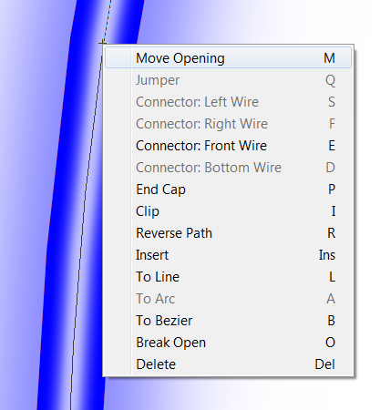
To bring up this menu, position the mouse over a vector or a point and double click with the left mouse button. Then move the mouse to the function that you want tp use and click the left mouse button once.

Not all functions will be available at all times.

Move Opening

This will move the opening of the tube from the current location to the location selected.
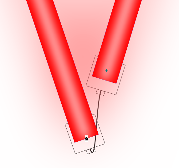
Jumper

Two tubes that are broken at a sharp corner can have a Jumper wire drawn to show that the two tubes are connected.
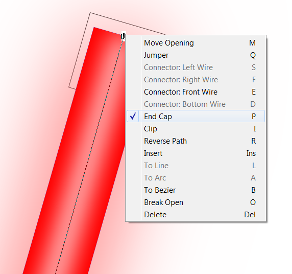
Connectors

There are four options for adding a Connector at a tube termination. Not all flex brands and products will have all options.

End Cap

Every tube termination needs a Connector or an End Cap.

Clip

A clip can be added at any point along the flex path. Clips are drawn as X's across the tube.

Do not add a clip on the corner of a path where the tube is rounded by the bend radius.

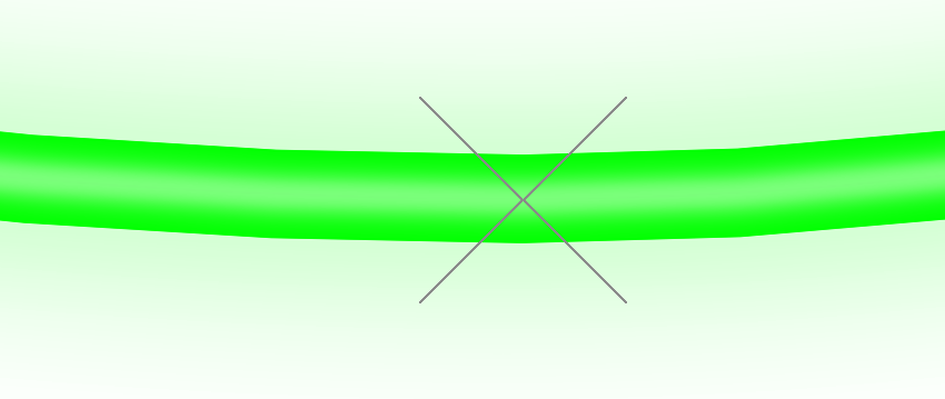
Clips are added on their own layer, so that you can toggle the display of the clips and select whether or not you Export them.

Reverse Path

This function will reverse the direction of the flex tube. All flex tubes have a direction, with a start point and an end point.

This is important because the end of the tube is determined by the Cut Resolution, and not the actual end of the flex vector path. You can see this when the centerline of the tube extends beyond the drawing of the tube. Therefore the end of the tube may not be in the ideal position. The tube will only be drawn when there is enough space for an entire section.

By reversing the path of the tube, you can then edit the exact position of whichever end of the tube is more critical.

Insert

This will insert a point at the location where you double clicked to bring up the menu.

To Line, Arc, or Bezier

These options will change the selected vector to whichever option you choose.

Break Open

This will open the loop at the position selected. It will not close the loop at a different location, use Move Opening for that.

Delete

This will delete the selected point. Please note in this tool that you can also delete points by just drawing a box around them with the left mouse button. This functionality is consistent with the normal Vector Edit Tool.


N/A
Was this helpful?          

Copyright (C) 2019-2025 Principal Industries